Auto Well Planner
Analytics Explorer's Auto Well Planner provides a simple and quick way to start your well planning. Based on user input, the application calculates proposed well paths and plots them on a map. The image below displays 2 different scenarios:

The required user inputs are the following:
-
Lease boundaries (shape files with lease boundaries or polygons)
-
Business rules: distance from edge, spacing, lengths
-
Existing wells within a lease
The calculated outputs are the proposed well paths and a visual representation (map) of the wells. Before beginning, make sure that the Map chart visualization is active.
Note: The Auto Well Planner only supports shape files the projected coordinate reference systems (XY coordinates). Shape files with geodetic CRS (Lat Long) are not supported.
To run Auto Well Planning:
-
Import or digitize the area of interest (leases, polygon) on the map. Import formats include shape files,
-
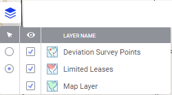
Make the shape layer active. In this example, the layer is the Limited Leases layer.
-
Select (highlight) the area of interest shape, for example, the lease block of interest.
-
Right click on the map and select Analytics Explorer > Auto Well Planner.
The dialog box opens. The application auto-fills fields where possible, but leaves you the option to select the input table and map columns. Mouse over the thumbnail below to see the expanded dialog.

| Input Data |
Input data includes the Shape file table and Coordinate reference system. The application reads the table names and column headers to intuit the correct fields to prepopulate. However, you can manually select or confirm as required:
|
| Well Plan Parameters |
All are required. Parameters are defined below the table. Parameters and defaults include the following.
|
- After you have selected or entered the input data and parameters, click Compute. Note that the well plans fill the designated area of interest, the number depending on the input parameters.
- When the computations are complete, the well plans appear on the map and an auto Well Planner table is created.
- You now have the option to save these well plans back to Kingdom. However, note that you can only save them IF you opened Analytics Explorer from Kingdom. See Saving well plans to Kingdom.