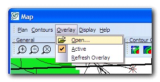
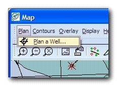
Before you plan a well, it is recommended that you load an overlay into the Directional Well Modules Map window.
To plan a well:
-
From the Directional Well module map windows menu, choose Overlay > Open and select an overlay that you have saved in your Map module. This will let you easily quality check the coordinates that you will be entering for surface, landing, and bottom hole locations.
-
Using the Zoom functionality, zoom in to the area in which you would like to plan a well:
-
In the Map menu bar, select Plan > Plan A Well
An option dialog box will pop up with the following options:
To Create a New Well in your database:
-
Select Create A New Well and press Continue.
-
Enter the required information.
UWI/API
|
Can either be UWI/API you will use for licensing the well or any name for the well
|
Symbol
|
For use on the map display
|
Select Survey Definition For Survey
|
We recommend that you put the proposed survey into the proposed survey category for clarity. This enables you to add the actual as-drilled survey into the actual category later on.
|
Well Label
|
: Optional
|
-
Press Continue.
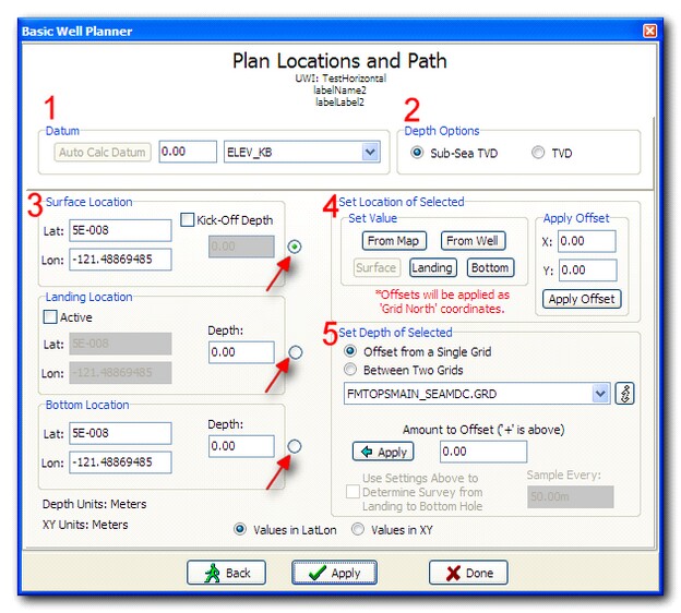
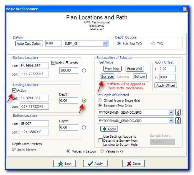
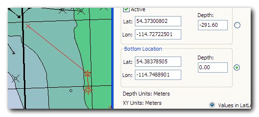
Plan Locations and Path:
-
Datum: Enter your datum, typically a GL (Ground Level) or KB (Kelly Bushing).
-
Auto Calc Datum: After you have picked a surface location, Petra can automatically calculate the datum based on the datum of the closest well.
2.
|
Depth Options: Set the dialog to use either Sub-Sea TVD (elevation) or TVD (depth from datum).
|
3.
|
Surface, Landing, and Bottom Hole locations
|
a.
|
These three groups down the left side of the dialog let you set the location and depth of each of the three points of the planned well. The radio buttons along the side (indicated with arrows on the dialog) are used to select which point you are currently working with.
|
b.
|
You can also simply type in a value in either XY or Lat Long for these three points, if you have them on a survey plan.
|
4.
|
Set Location of Selected
|
a.
|
This box is used to set the location of whichever of the three planning points (#3 on the dialog) you have selected.
|
i.
|
From Map Allows you to set the location by clicking on the map
|
ii.
|
From Well Allows you to set the location based on another well on your map
|
iii.
|
Surface Sets the location to be the same as the Surface location
|
iv.
|
Landing Sets the location to be the same as the Landing location
|
v.
|
Bottom Sets the Location to be the same as the Bottom location
|
b.
|
Apply Offset in addition to being able to set the location based on any of the above 5 options, you can also apply an offset (for example if you knew you wanted the surface location of your new well to be a certain distance away from surface location of a previous well). Please note that all offsets are applied in Grid North, not True North.
|
a.
|
Used to set the depth of whichever of the three planning points (#3 on the dialog) you have selected.
|
i.
|
Offset from a Single Grid Allows you to set the depth based on a gridded surface. Select the surface from the drop-down list below. You can also enter a depth offset (positive for shallower, and negative for deeper) to set the point above or below a target.
|
ii.
|
Between Two Grids Allows you to set the depth based on two grids. Petra will place the point halfway between the two gridded surfaces in depth.
|
b.
|
Press the Apply button to apply the changes to your selected planning point.
|
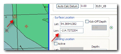
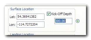
Press Apply to see your changes in a profile view.
A more detailed workflow sequence example is:
Pick a Surface Location from a map:
1.
|
Make sure the radio button next to Surface Location is checked, and click the From Map button:
|
2.
|
Petra will show you the map. Click on the surface location for your well. Petra will automatically place a well symbol at the surface location and populate the dialog box with the XY or Lat Long of the location.
|
a.
|
If you would like to apply an offset or a Kick Off Depth, you can make those changes now in the dialog.
|
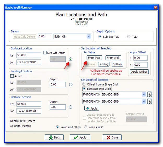
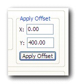
Create a Landing Location from offsets:
1.
|
Check the Active checkbox under Landing Location, make sure the radio button next to Landing Location is checked, and click the Surface button to set the Landing Location from the Surface location of the well:
|
2.
|
Now apply an offset to that Landing Location of X=0m and Y=400m (0ft and 1200ft respectively). The map will change to reflect your new landing location directly north of your surface location.
|
3.
|
Apply a depth for your Landing Location by either entering a depth in the Depth box, or by setting an offset to a grid.
|
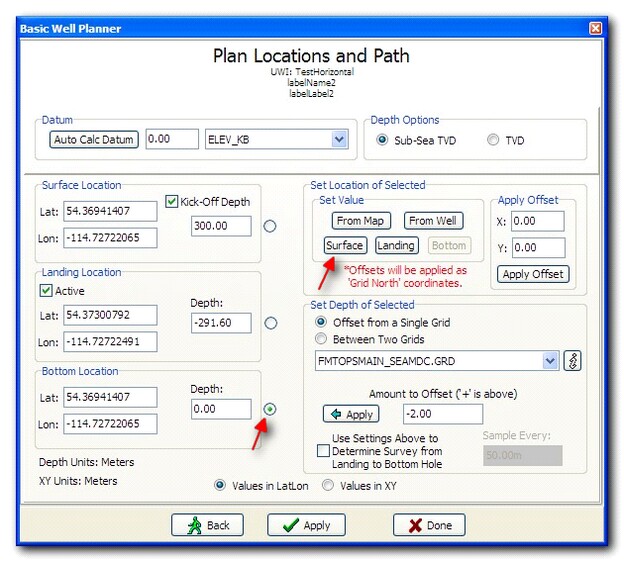
Pick a Bottom Location from the map.
1.
|
Make sure the radio button next to Bottom Location is checked, and click the From Map button.
|
2.
|
Petra will show you the map. Click on the bottom location for your well. Petra will automatically place a well symbol at the bottom location and populate the dialog box with the XY or Lat Long of the location.
|
3.
|
Apply a depth for your Bottom Location by either entering a depth in the Depth box, or by setting an offset to a grid.
|
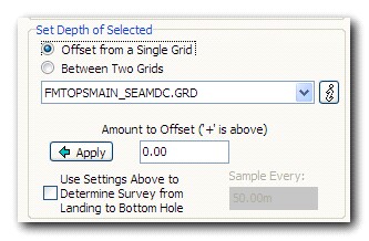
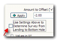
If you simply add a depth point for the Landing Location and another depth point for the Bottom Location, Petra will plan the well in a straight line between those two points. If you have significant topographical changes along the well path, you may wish to sample the well to a surface (or between two surfaces) along the wellbore.
To do this, check the Use Settings Above To Determine Survey from Landing to Bottom Hole checkbox, ensure your settings are correct (sampling to one or two grids, offset) and press Apply.
The difference is shown below.
With two points along the wellbore (Landing Location and Bottom Location):
Sampling to the Top of Coal Seam surface:
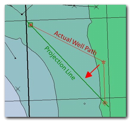
Press Apply to add your newly planned well to the Petra database. To make changes to your well, simply change the desired values in the dialog and press Apply. When you are satisfied with your planned well, you can press Done to exit the planning screen.
Note About Projected View:
When working with a horizontal well with an offset (or offplane) landing location and a lateral bend, Petra projects the well path onto a straight line drawn between the surface and bottom hole locations. The difference in the projection of grids and borehole path may cause an apparent depth issue in the projected view with respect to the landing location:
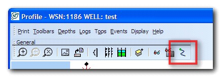
To resolve this apparent discrepancy, you can view your profile un-projected, or along the actual well path. To toggle this setting, press the Enable/Disable TVD vs Offset Mode button on the menu bar:
The un-projected view will show the actual landing location in relation to the surface in question:
|