|
This function can be used to compute the percentage of pay that is "continuous" between a well and its neighbors.
Pay in each well is represented by a selected "pay flag" (0 or 1) digital log curve over one or more Zone intervals. Depth matching in wells is determined by Zone tops and bases. Pay is considered continuous between two neighboring wells when both zones contain a non-zero pay flag value. The continuity calculation computes the percentage of total shared pay footage to total pay footage, with adjustments made for differences in thickness between wells.
Petra compares the amount of continuous pay between a node well and its neighbor wells. For each well, pay continuity is computed between the well and its nearest neighbors. The value stored in each well zone item is the distance-weighted average of the continuity values computed for each neighboring well.
The utility of a continuity calculation is only as good as the constraining zone definitions. This calculation works best on a zone with fairly tight depth limits and with few washouts. A thick zone definition containing multiple pay streaks will generate worthless numbers.
To open the Log Curve Substitute tool, select Compute>From Logs>Substitute from the menu bar at the top of the Main Module
Compute tab
Check the boxes and set the names of the zone items you want to compute.
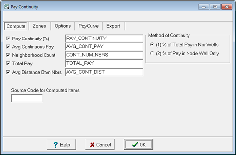
Pay Continuity (%) - Zone Item Name for storing pay continuity percentages. Continuity values range between 0.0 and 1.0.
Avg Continuous Pay - Zone Item Name for storing average number of feet (or meters) of continuous pay in the "node" well.
Neighborhood Count - Zone Item Name for storing the count of the number of neighbors used in the calculation for the "node" well.
Total Pay - Zone Item Name for storing total number of feet (or meters) of pay in the "node" well.
Method of Continuity - Select method 1 or 2 as described above. Method 1 calculates continuity as a percent of the sum of the pays in both wells, while Method 2 calculates continuity as a percent of the total pay in the node well.
Source Code for Computed Items - Enter the source code for storing any zone items.
Method 1
This method computes continuity as a percent of the sum of the pays in both node well and neighbor well.
CONTINUITY = (AC+BC)/(AT+BT)
Where
AC = #ft continuous pay in "node" well A
BC = #ft continuous pay in neighbor well B
AT = total #ft of pay in "node" well A
BT = total #ft of pay in neighbor well B

In the above example, Zone I is 100% continuous between wells A and B. Zone II is discontinuous, i.e., 0% continuous. Zone III would be (10'/15') or 66% continuous. For well A, total continuity, for zones I, II and III, would be 66%.
Where, AC=10, BC=10, AT=20, BT=10 CONT=(10+10)/(20+10)=20/30=0.66666
Method 2
his Method computes continuity as a percent of the pay in the node well only.
CONTINUITY = (AC)/(AT)
Where
AC = #ft continuous pay in "node" well A
AT = total #ft of pay in "node" well A
In the above example, Zone I is 100% continuous between wells A and B. Zone II is discontinuous, i.e., 0% continuous. Zone III would be (5'/10') or 50% continuous. For well A, total continuity, for zones I, II and III, would be 50%.
Where, AC=10, AT=20 CONT=10/20=0.50
Zone tab
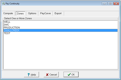
Select one or more zones for which you want pay continuity computed. Petra uses zone interval definitions to limit the interval calculated. If your zone intervals are defined by the default -99999.0 to +99999.0 MD, you will need to define the zone in the Main Module.
Options tab
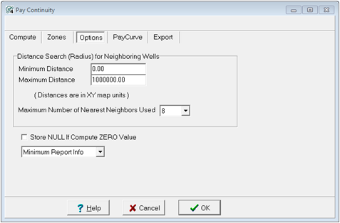
Distance Search (Radius) for Neighboring Wells - This section allows to limit the minimum and maximum distance between a "node" well and its neighbors. This limit is in XY map units.
Maximum Number of Nearest Neighbors Used - set the upper limit on the number of neighboring wells used to compute values at each node well. For example, if 8 is specified the 8 nearest wells to the node well are used. The neighbors must also meet the min-max radius condition. In other words, if a well is too far or too close than the minimum or maximum distances, it will be ignored.
Store NULL If Compute ZERO Value - Check this option when you want null values stored in place of zero pay values. Normally, if a well's pay flag curve accurately reflects the logs and has no pay, the computed values should be ZERO.
Report Info Petra can generate a report of the continuity calculation called CONTINUITY.TXT in the projects Reports folder. This controls the level of report information generated and can be set to minimum, detailed, or no report.
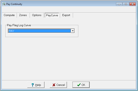
Pay Curve tab
Choose the pay flag curve used to represent pay in each wells. A pay flag curve should have values of 0 for non-pay and 1 for pay. Only wells containing this curve will be used.
Export tab
This section allows for the export "control point" files for Pay Continuity, Avg Continuous Pay, and Total Pay. There will be one set of files for each zone selected. Each file contains Wsn, Lat, Lon, Z values for the computed data. Points are computed at the mid-point between a node well and each neighboring well.
These files can be loaded into the map module for posting and contouring using the "external control point" option.
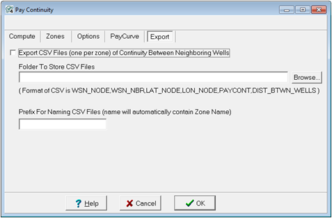
Folder To Store LatLonZ File - Click the "Browse" button to select the folder where the control point files will be saved.
Prefix - You may enter a text string that is used to prefix each of the file names.
Files names are generated using the following format: Prefix_ZoneName_ItemName.xyz
Reference: "Improved Techniques for Evaluating Carbonate Waterfloods in West Texas", by George and Stiles, SPE, Nov 1978.
To calculate Pay Continuity, in the main module go to Compute>From Logs>Pay Continuity
|