Petra displays cross sections as a fence diagram inside the 3DViz module. The 3DViz module uses a special *.X3D file to position a cross-section image file inside the 3D volume.
Multiple cross section images may be shown, generating a fence diagram. Multiple cross sections, particularly at high resolution, will require more memory and will render more slowly.
Creating a X3D File
Cross Section: File > Print To > 3DViz
The first step to displaying a cross section on the 3DViz module is to create a X3D file from the Cross Section module. This process creates both the cross section image and the X3D file, which correctly positions the cross section image file inside the 3DViz volume.
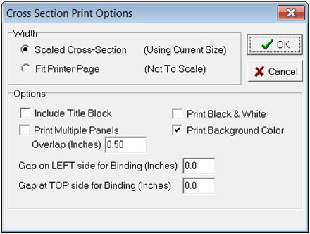
On the Print Preview Tool, select either:
File > Export 3DViz File
File > Export 3DViz File (Clipped)
Adding a Cross Section
3DViz: Surfaces > Grids
Main Toolbar:
Petra displays cross sections as a fence diagram inside the 3DViz module.
Cross Section
Selects the cross section to display on the 3DViz Module.
By default, this tool will look in the project directory for *.X3D files created by the Print Preview tool.
Color
Sets the background color of the cross section. By default, this is white.
Opacity
Sets the opacity of the cross-section in the 3DViz Module.
Rendering Resolution
Sets the resolution of the cross section on the 3D module.