Drainage Polygons
Drainage polygons are user-defined polygons drawn around wellbores which can be further utilized for a number of workflows: well planning, reservoir evaluation (over/under utilization), calculation of volume drained, and much more. Note that the polygons can be exported as shapefiles and used in other packages such as Spatial Explorer where such calculations can be made. See Exporting drainage polygons for more information.
After running the drainage polygon calculations, the drainage area of each borehole is calculated according to the specified parameters.
To create drainage polygons:
-
In Spotfire, right-click anywhere on the table containing the deviation survey points for the selected wells and select Analytics Explorer > Drainage Polygons. In any images that follow, this table is the Deviation Survey Points table.
-
Enter the desired input data and polygon parameters.
-
Click OK to run the calculations for Draining Map Analysis. Note that if you have a large number of boreholes selected, the calculations could take some time.
-
(Optional) You can save your input data and polygon parameters as a template for future use. After you have completed both sections, click Save Template.
The dialog box contains the following inputs and parameters to define the polygons.
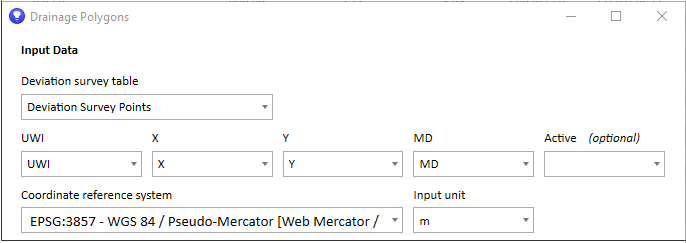
Input Data
The input data is a selected table such as deviation survey points with the required columns: UWI, MD, X, and Y. Analytics Explorer will automatically populate the columns for these fields if the column header can be recognized. However, if your column headers are not recognizable, you can map each column to the UWI, MD, or X/Y/Z field. To map, simply click the dropdown and select the appropriate column.
After you have run the drainage polygon calculation, the Input Data section becomes read only. To make changes, click Edit.
To map the drainage polygons correctly in Spotfire, Analytics Explorer requires the coordinate reference system (CRS) of the incoming data. The CRS defaults to WGS 84 (3857) with an input unit of meters which is the default for that EPSG. It is important that you know the CRS of the incoming data and the unit of measure. If it is different than Spotfire's, then select the source data's CRS from the dropdown list. Analytics Explorer will make the conversion to WGS 84 (3857) to ensure accurate mapping in Spotfire.
The input unit (feet or meters) can sometimes differ from the CRS unit. For example, NAD27 UTM Zone 14N is a common coordinate reference system for West Texas. However, this CRS unit is meters. Therefore, if your deviation survey XY data is in feet, and you do not select feet as the input option, your data will not map correctly. More information on the EPSG Geodetic Parameter Dataset can be found online.
Polygon Parameters
In general, polygon parameters can be specified by entering a global value, or can be read from a table to allow for borehole-specific values. If you select the table option, the table and column fields appear. The dialog box stays open after you apply the polygon parameters to the map, so a useful approach is simply to change the parameters until you find the best result.
Polygon Parameters include the following:
| Polygon style |
Styles include overlapping and non-overlapping. The default is non-overlapping. If the polygon style is non-overlapping, then the half-length stops at the edge of the neighboring borehole. |
|
Half-length |
The distance from the borehole deviation survey points to the edge of the polygon (the polygon radius). The half-length can be fixed (the same for all boreholes), or from a table by UWI. If the half length is from a table that includes a half-length column by UWI, you need to specify the table, UWI column, and Length column. |
| Half-length distance | The default is 300 meters or feet. You can specify the half-length distance for both overlapping and non-overlapping polygons. However, remember that if the style is non-overlapping, the polygon will stop at the contact point with the neighboring polygon. |
| Cap style | Cap style is a second method to shape the toe of the polygon. Options include round, flat, and square. |
|
Azimuth (0-180) |
Determines the shape of the toe of the polygon. The azimuth is measured from the coordinate reference system's true north. |
| Start depth | The start depth of the polygon. Start depth can be specified, or can be read from a table. For example, if you have a zone table, you may want to specify the heel location as the start depth. |
| End depth | The end depth of the polygon. The same rules apply for end depth, which can be specified as Last MD, a specified MD, or read from a table. |
See Drainage polygon examples for visual representations and explanations.