|
Raster logs are scanned copies of paper logs saved as image files. In order to plot the correct part of the picture at the right depth on a cross section, Petra requires computer-recognizable depths to be assigned to depths printed on the original log. This tool can set headers, footers, and scales, as well as left and right edges. Petra saves these calibration points to a associated (*.LIC) text file for every group name.
Depth Calibration Toolbar
The depth calibration toolbar is probably the easiest way to rapidly work with depth and other calibration points.
To display this toolbar, select View>Depth Calibration Toolbar.

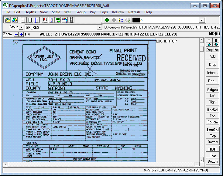
Scroll to Top and Base
These buttons simply jump to the shallowest or deepest depth calibration point.
To jump to the top calibration point, select either the "T" or up arrow button.

The scroll to top and scroll to base buttons
Adding, Changing, and Dropping Depth Calibrations
Depth calibration points translate depth marks on the image into depths that Petra can use. The portion of the image that can be displayed on the cross-section is only the section within the range of the calibration depths. Portions above the shallowest depth and below the deepest depth will not be displayed.
To add a depth point, select the "Add" button on the toolbar, or Depths>Add Depth Point on the menu bar at the top of the Calibration Tool Bar. Note that Petra will draw a horizontal cursor over the image. Position the horizontal cursor over the desired image exactly at the depth you wish to pick, then click the left mouse button. Finally, enter the depth value. After entering the depth value, the screen will redraw showing the new calibration depth point. Repeat the process for each depth reference point.
To change the location of the depth, click and drag the depth marker using the left mouse button.
To edit the value of an existing depth, click on the depth line with the right mouse button and enter a new value.
To delete an existing detph calibration point, select Depths>Delete Depth" option menu or the Delete button located at the top of the Calibration Tool Bar. After invoking the delete function, click the left mouse button on the depth marker to be deleted. The screen will redraw once the marker is deleted.
You can also delete all depth references using the Depths>Delete All Depths...
Automatically Interpolating Depths
This tool automatically creates depth points by a given interpolation increment between the uppermost and lowermost calibrated depths. Since Petra already scales between registered depths, automatically adding a lot of new points does not aid in the overall calibration of the raster log. Creating a bunch of extraneous depth calibration points is often more trouble than it's worth - it's generally better to look for the small black interpolated depth lines, and add new depth points where necessary. Most rasters only need a few depth calibration points, and even extremely distorted ones usually won't need more than a dozen.
To automatically create depth points, select the "Interp" button on the toolbar or select Edit>Interpolate Depths. Here, select the depth increment - Petra will interpolate between depth calibration points using the set footage.
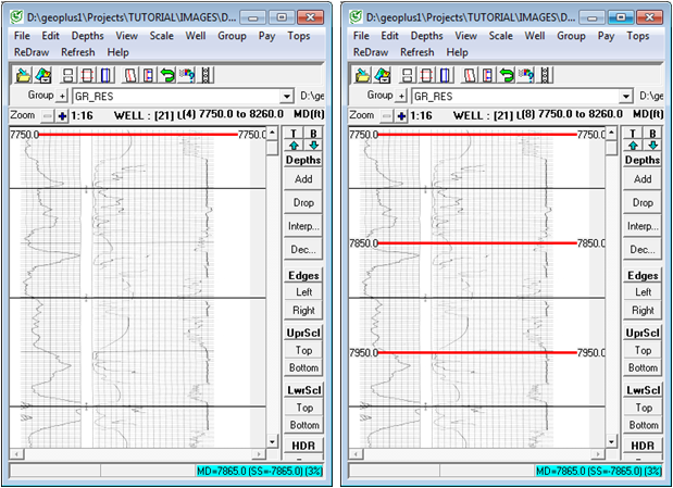
Before (left) and after (right) depth point interpolation. Note the automatically interpolated depths in thin black lines remain unchanged.
Decimating Depth Calibrations
This tool decimates depth calibration points in between the upper- and lowermost points. This can be useful for removing unnecessary calibration points created by the interpolation tool or an overzealous interpreter.
To decimate depth points, select the the "Interp" button on the toolbar or select Edit>Interpolate Depths. Here, select the depth increment - Petra will interpolate between depth calibration points using the set footage.
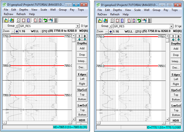
Before (left) and after (right) decimating every third depth point
Left & Right Edges
The left and right edges set the useful boundaries of the group image. These boundaries can be useful for trimming extra white space on the sides of the image.
To set the left and right edges, select the "Left" or "Right" button on the toolbar, or select Edit>Set Left-Most Edge or Edit>Set Right-Most Edge on the menu bar at the top of raster calibration tool.
Next, position the line at the relevent part of the image and left click. For the left side, for example, set the edge on the left side fo the image. Note that the edges will have a blue triangle pointing inward. If the triangle is pointing out away from the center of the image, it's on the wrong side.
To change the location of either edge marker, click and drag the marker using the left mouse button.
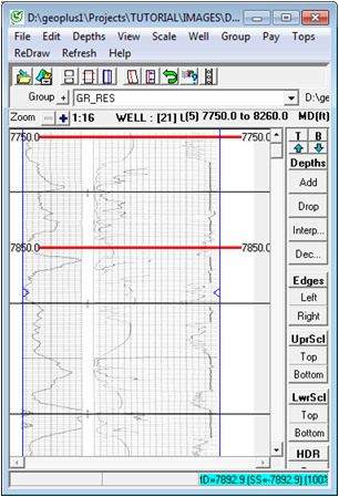
Blue left and right edges added to a raster log. Note the small triangles pointing inward.
Upper & Lower Scale
The scales help define what the curves on the raster log actually represent. Scales can be plotted in the raster image's track on both the Cross Section Module and Log Correlation Tool.
To set the scales, select the "Top" button on either the "UprScl" or "LwrScl" section of the the toolbar, or select Edit>Upper Scale Header>Set Upper Scale Top / Edit>Lower Scale Header>Set Lower Scale Top on the menu bar at the top of the raster calibration tool. Position the line at the upper part of the scale, and left click. Note that Petra will draw a green line on the image.
Next,select the "Bottom" button on either the "UprScl" or "LwrScl" section of the the toolbar, or select Edit>Upper Scale Header>Set Upper Scale Bottom / Edit>Lower Scale Header>Set Lower Scale Bottom on the menu bar at the top of the raster calibration tool. Position the line at the bottom part of the image, and left click. Petra will draw the section in between the two lines with a green overlay. Note that this overlay is just for positioning, and won't appear on cross sections.
To change the location of either edge marker, click and drag the marker using the left mouse button.
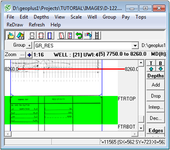
A lower scale set at the bottom of an image
Headers
Headers designate the part of the image occupied by the image's header, which usually contains well information, dates, and other relevant wireline information.
To set the header, select the "Top" button on the "HDR" section of the the toolbar, or select Edit>Log Header>Set Log Header Top on the menu bar at the top of the raster calibration tool. Position the line at the upper part of the scale left click. Note that Petra will draw a green line on the image.
Next, select the "Bottom" button on the "HDR" section of the the toolbar, or select Edit>Log Header>Set Log Header Bottom on the menu bar at the top of the raster calibration tool. Position the line at the upper part of the header left click. Petra will draw the section in between the two lines with a pale blue overlay. Note that this overlay is just for positioning, and won't appear on cross sections.
To change the location of either header marker, click and drag the marker using the left mouse button.
Display Gaps
The portion of an image interval between 2 calibrated depths can be hidden during cross-section display if that interval is tagged as a "display gap". Gaps can result when calibration files are merged and there is a gap between the sections being merged. You can manually define a depth interval to be a gap by clicking the left mouse button between 2 calibration depths while holding down the control key. Each time you click, the gap is toggled on or off. Display Gaps are shown in the calibration screen as a "grayed out" portion of the image.
Saving the Calibration File
Choose the "File>Save Calibration As..." menu to save a file containing the calibration data, image name, depth references, etc. This will also update the Petra database with a reference to the calibration file which is now associated with the current well.
The "File>Save Calibration" will save the current calibration being modified.
Log Image Calibration files have a file extension of ".LIC"
Loading a Calibration File
You can load and modify a previously saved calibration file using two methods.
First, the "File>Load Calibration File" menu allows you to choose the specific calibration file to be loaded. The image name will be read from the calibration file and the image will be opened and displayed.
Secondly, the "File>Load Calibration For Group" menu will retrieve the name of the calibration file from the Petra database which is associated with the current well and image group name.
|