Selecting and saving data
Spatial Explorer provides several different ways to select data on the map.
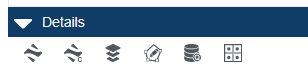
The data selection tools include:
| Toolbar Icon | Functionality |
|---|---|

|
Select items on the map by drawing a rectangle |

|
Select items on the map by drawing a polygon |

|
Select a single item on the map (use the Control key [Ctrl] to select multiple items individually) |

|
Select all items available on the map |

|
Select all items currently shown in the map pane. The Details of the selected data type will display in the Details pane below the map. |
After you select the data, the items are listed in the Details pane below the map. You have the following options available from the Details pane toolbar. Hover over each to see the description:
Save to Kingdom | Save to Kingdom Culture | Save to Shapefile | Copy to Editable Polygon | Well Query | Save Buffer Layer
You can save data from Spatial Explorer to the following:
-
Shape file
-
Culture file
-
Buffer layer
-
.CSV file
-
SDE database (in some cases)
-
Drainage bubble
-
GeoTiff file,
-
Editable polygon layer
-
XML file
-
Kingdom well subset.
Details pane
After you select items on the map, the Details pane at the bottom of the Spatial Explorer workspace displays the list of identified data, including wells, deviation surveys, grids, polygons, and culture groups among others. After you have project data identified, you can save the data.
You can modify the data columns that display for the selected data by clicking  and then clearing or selecting the check boxes next to the column names you want to hide or show. This does not affect what data you save, only the data that displays in the Details pane.
For lines, you can save well plans to Kingdom from a shape file, SDE database, geodatabase, feature service, or map service. You can also save well subsets to Kingdom from the same data sources.
To save a data from a layer, you must first make that layer active by clicking Make Layer Active for the layer you want in the Layers column.
Data saved from Kingdom to Harmony Enterprise
Some reservoir properties of Kingdom wells can be saved to Harmony Enterprise using Spatial Explorer. For more information, see Kingdom to Harmony Data Transfer.
Data saved from Kingdom
The following table summarizes the data you can save from Kingdom to a shape file, SDE database, drainage bubble, buffer layer, GeoTIFF file, or XML file that can be imported into Harmony Enterprise. You can also publish items to an ArcGIS portal.
| Saving from Kingdom
|
||||||||
|---|---|---|---|---|---|---|---|---|
| Kingdom Data Type | To shape file | To SDE Database | Create Drainage Bubble | Create Buffer Layer |
To GeoTiff |
To Editable Polygon Layer |
To ArcGIS Portal |
To Harmony Enterprise |
|
Wells |
X |
X |
|
X |
|
|
|
X |
|
Well Deviations |
X |
X |
X |
X |
|
|
|
|
|
Well Plans |
X |
X |
X |
|
|
|
|
|
|
2D Surveys |
X |
X |
|
X |
|
|
|
|
|
3D Surveys |
X |
X |
|
X |
|
|
|
|
|
Polygons |
X |
X |
|
X |
|
X |
|
|
|
Culture Groups |
X |
X |
|
X |
|
X |
|
|
|
Contours |
X |
X |
|
X |
|
X |
|
|
|
Control Points |
X |
X |
|
X |
|
|
X |
|
|
Horizons |
|
|
|
|
X |
|
X |
|
|
Grids |
|
|
|
|
X |
|
X |
|
|
Fault Segments |
|
|
|
|
X |
|
|
|
|
Fault Grids |
|
|
|
|
X |
|
|
|
Data saved to Kingdom
You can save well plan data from feature services, map services, shape files, SQL Server SDE databases, and geodatabases to Kingdom. You can also save drainage bubbles from deviation surveys and buffer layers from points, polygons, and lines (including deviation surveys) to Kingdom. Buffer layers visually depict a specified distance from a point, line, or polygon as an indicator for a minimum distance to maintain from the point, line, or polygon. Drainage bubbles serve as a visual indicator of where production is occurring along the length of a deviated well based on the well path and a starting inclination.
| Saving to Kingdom | ||||||
|---|---|---|---|---|---|---|
|
Data Saved |
Data Source |
|||||
| Shape file | SDE Database | Geodatabase | Feature Service | Map Service |
Polygon |
|
|
Well Plan (save as well plan) |
X |
X |
X |
X |
X |
|
|
Well Subset |
X |
X |
X |
|
|
|
|
Buffer Layer |
X |
X |
X |
|
||
|
Drainage Bubble |
X |
X |
X |
|
||
|
Shape file |
X |
X |
X |
X |
||
|
Ellipse |
X |
X |
X |
|
||
|
Polygon |
|
|
|
|
|
X |
Saving data to and from Kingdom
The following instructions explain how to save data other than well plans and well subsets to and from Kingdom using Spatial Explorer. Refer to separate instructions for saving well plans and saving well subsets.
When saving data from an Energy map service data source, keep in mind that for certain data types you may need to make the Detail data layer the active layer. Overview layers serve as a display layer only and do not contain any selectable data.
- Select the data layer you want to save in the Layers list and click
 to make the layer active.
 - Choose the selection tool you want to use from the map toolbar and select the items you want to save. When digitizing a polygon, you must double-click the last point on the polygon to complete the selection.
- The Details Panel opens with the selected data displayed.
- If needed, filter the list of selected items by attribute to further refine your selection.
- Select Save to Shapefile from the Save as list, and then click
 .
. - Depending on the data in the active layer, you many need to select the specific data you want to save. Well Explorer provides a default list to which you can add or subtract items. After you have selected the items you want, click OK.
- Browse to where you want to save the file, type the file name, and then click Save.
You can also save data from one shape file to a new shape file following the steps above. For example, if you have a project that covers a small geographic area, but you have a lease boundary shape file that covers a much broader area, you can select the lease blocks you want for your project from the shape file and save them as a new shape file.
-
Select the data layer you want to save in the Layers list and click to make the layer active.
- Choose the selection tool you want to use from the map toolbar and select the items you want to save. When digitizing a polygon, you must double-click the last point on the polygon to complete the selection.
- The Details Panel opens with the selected data displayed.
- Select Save to SdeDatabase from the Save as list, and then click
 .
. - Type the path to the SDE database server in the Address field, and then click Next. If you are connecting to the specified SDE server for the first time, you will be prompted for a username and password. If you have connected to this server before, select the option Use existing credentials if available to avoid the prompt for a username and password.
- Follow the remaining steps in the wizard to save the data to the SDE database. These steps include selecting an SDE database and database table where you want to save the data and mapping the data attributes you are saving to data attributes in the SDE database you selected. If you need more detailed instructions, click the Show hints link.
- Select a layer with the data you want to save in the Layers list and click to make the layer active.
- Choose the selection tool you want to use from the map toolbar and select the items you want to save. When digitizing a polygon, you must double-click the last point on the polygon to complete the selection.
- The Details Panel opens with the selected data displayed.
- Select Create Buffer Layer from the Save as list, and then click
 .
. - Type a name for the buffer layer in the Layer Name field.
- Define a distance from the selected items for the buffer size (the default is 100 meters).
- If needed, select the option to calculate the inner buffer. This option applies only to polygons and creates the buffer on the inside of the polygon(s) rather than the outside.
- If needed, select the option to display the buffer area only. This option applies only to polygons and restricts the fill color to the area defined by the buffer area only.
- Define the line color, line size, and fill color for the buffer area.
- When you have finished setting all the options, click OK.
You can only create an ellipse layer for well data.
- Select a well data layer you want to save in the Layers list and click to make the layer active.
- Choose the selection tool you want to use from the map toolbar and select the wells you want to create an ellipse for. When digitizing a polygon, you must double-click the last point on the polygon to complete the selection.
- The Details Panel opens with the selected wells displayed.
- Select Create Ellipse Layer from the Save as list, and then click .
- Type a name for the ellipse layer.
- Define a length for both the long and short axis of the ellipse.
- Define the angle for the long axis or accept the default.
- Define the line color, thickness, and style for the ellipse or accept the default.
- Define the fill color for the ellipse or accept the default.
- Click OK to create the layer.
You can only create an ellipse layer for well data. Create an ellipse from zone data when you want to illustrate well drainage areas on the Spatial Explorer map.
- Select a well data layer you want to save in the Layers list and click to make the layer active.
- Choose the selection tool you want to use from the map toolbar and select the wells you want to create an ellipse for. When digitizing a polygon, you must double-click the last point on the polygon to complete the selection.
- The Details panel opens with the selected wells displayed.
- Select Create Ellipse Layer from the Save as list, and then click .
- Type a name for the ellipse layer.
- Select the From Zone tab.
- On the Drainage Area tab, select the zone and zone attribute containing the drainage area data for the selected well or wells in the Zone and Attribute fields.
- Select the unit of measure to use for the drainage area data in the Area Units field. The default value is acres.
- If you want to ignore drainage area values outside of a specified range, select the option Ignore Data Outside Range and then enter the minimum and maximum values of the range you want to use.
- On the A/B Ratio tab, if you want to determine the ratio of the long and short axes of the ellipse using zone and zone attribute values, select the Zone option and then select the zone and zone attribute containing the ratio value. This method is useful if you have selected multiple wells and want different ratios for each well. Otherwise, select the Constant option and enter a constant value. For example, a value of 2 creates every ellipse with the long axis twice as long as the short axis.
- If you want to enlarge or shrink the size of the ellipse(s) drawn on the Spatial Explorer map, select the option Multiply Factor and enter a multiplier value. For example, a value of 2 doubles the size of any ellipse and a value of .5 reduces the size of any ellipse by half. This does not change the ratio of the long axis to the short axis.
- On the Orientation tab, if you want to change the alignment of any well ellipses using zone and zone attribute values, select the Zone option and then select the zone and zone attribute containing the orientation value. This method is useful if you have selected multiple wells and want different orientations for each well. Otherwise, select the Constant option and enter an azimuth value.
- Define the line color, thickness, and style for the ellipse or accept the default.
- Define the fill color for the ellipse or accept the default.
- Accept the default value to draw an ellipse on the base map or select the Rectangle option to draw a rectangle instead.
- Click OK to create the ellipse layer.
You can only create a drainage bubble for a deviation survey.
- Select a deviation survey data layer you want to save in the Layers list and click to make the layer active.
- Choose the selection tool you want to use from the map toolbar and select the items you want to save. When digitizing a polygon, you must double-click the last point on the polygon to complete the selection.
- The Details Panel opens with the selected data displayed.
- From the Save as list, select Create Drainage Bubble, and then click .
- Type a name for the drainage bubble in the Layer Name field.
- Select the distance from the borehole path for the drainage bubble.
- Specify whether to measure distance in feet or meters.
- Select the Start at and End at options to define where the drainage bubble starts and stops along the borehole path. Options include MD, inclination, formation top, or zone and zone attribute.
- Define the display attributes of the drainage bubble. This includes the border color, thickness, and style, as well as a fill color.
- Click OK.
You can create an editable polygon layer from a contour layer, a culture layer, or a polygon layer.
- Select the data layer you want to save in the Layers list and click to make the layer active.
- Choose the selection tool you want to use from the map toolbar and select the items you want to save. When digitizing a polygon, you must double-click the last point on the polygon to complete the selection.
- The Details Panel opens with the selected data displayed.
- From the Save as list, select Copy to Editable Layer, and then click .
- Type a new name for the editable layer or select the name of an existing editable polygon layer to add the selected polygon to the existing layer.
You can save grids, horizons, fault segments, and fault grids from Kingdom to a GeoTiff file.
- Select the data layer you want to save in the Layers list and click to make the layer active.
- Choose the selection tool you want to use from the map toolbar and select the items you want to save. When digitizing a polygon, you must double-click the last point on the polygon to complete the selection.
- The Details Panel opens with the selected data displayed.
- From the Save as list, select Save to GeoTiff file.
- As an option, select Save grid values if you want to save the values of the original grid with the GeoTiff file.
- As an option, select Save in original resolution. This saves the GeoTif ffile as interpolated at the scale selected when you save the file. Selecting this option may cause the GeoTiff image to pixelate if you open and expand or shrink the image after saving it.
- Click Next.
- Type the name of the GeoTiff file and then click Save.
You can publish grids and horizons from Kingdom to an ArcGIS portal.
- Select the data layer you want to save in the Layers list and click to make the layer active.
- Choose the selection tool you want to use from the map toolbar and select the items you want to save. When digitizing a polygon, you must double-click the last point on the polygon to complete the selection.
- The Details Pane opens with the selected data displayed.
- If you have selected more than one item, select one item from the list you want to save as a GeoTiff file.
- From the Save as list, select Publish to ArcGIS Portal, and then click .
- Complete the information in the Publish Image or Feature Service window.
- If needed, update the name of the service you are publishing in the Service name field.
- Review the portal settings in the Portal Url field to confirm they are correct. If you have not yet configured an ArcGIS portal, click Portal Settings. For more information about portal settings, see configuring ArcGIS.
- Add any tags you want to use as search terms for the service in the Tags field.
- Select the groups you want to share the service with from the lists of available groups. If no groups are listed, click Get Groups.
- If needed, provide a summary description of the service in the Summary field.
- Click Publish.
Saving well plans to Kingdom
Follow these steps to save well plan data to your project. You cannot save information from WMS services and you cannot save any line data other than well plans. Note that this option is not available unless the map has a data layer with well plans that you have selected.
- Select the well plan data layer you want to save to Kingdom.
- Choose the selection tool you want to use from the map toolbar and select the items you want to save. When digitizing a polygon, you can drag and drop the midpoint markers of line segments to change the shape of the polygon, and you must double-click the last point on the polygon to complete the selection.
- The Selected Features window opens with the selected data displayed.
- If needed, filter the list of well plans by attribute to further refine your selection.
- Click Next.
- Follow the remaining steps in the wizard to save the data to Kingdom. If you need more detailed instructions, click the Show hints link.
Saving well subsets (Kingdom only)
Depending on the data layer you select, you can create a static well subset from the data you select. You can save a well subset from any layer containing Kingdom wells (you can also save that data to a shape file or SDE database, as described above).
- Select a data layer containing Kingdom wells.
- Choose the selection tool you want to use from the map toolbar and select the items you want to save. When digitizing a polygon, you must double-click the last point on the polygon to complete the selection.
- The Details Panel opens with the selected wells displayed.
- Select Save to Subset from the Save as list, and then click .
- Type the subset name and then click OK. The subset is now available in the list of subsets in Spatial Explorer, Well Explorer, and Kingdom.